オペアンプ
はじめに
c12880ma分光器をRaspberry Pi Picoで使えるようにするため、周辺回路で使っているオペアンプ(NJM77701F)とデジタルポテンショメータ(MAX5477)についての使い方とメモ。
c12880maのクロックなどは最小3.0Vでも動作するようであるが、5.0Vが推奨されている。Video信号のインピーダンスは150Ωが推奨されており、次のようなコメントが記載されている。
”ビデオ端子の消費電流の増大により、チップ温度は上昇し暗電流が増加します。そのため、ビデオ出力端子にはバッファアンプを接続して、できるだけ電流を流さないようにしてください。”
そこで、NJM77701Fを2個使い、1つをバッファアンプ(ボルテージフォロア)に、もう一つを反転増幅回路とし、5V→3.3Vに変換している。
デジタルポテンショメータMAX5477は反転増幅回路の増幅率とオフセット値を設定する目的で用いている。
なお、c12880maのVideo信号のレートはクロック周波数が設定されているが、露光時のクロックである必要はなさそうなので、Raspberry Pi PicoのADCでも動作させることができる。MicroPythonで300ksps(45ksps程度)でていたと思う。
MAX5477のコード
MAX5477のMicroPythonのコードは以下の通り、データシートをよく読まずに不揮発性メモリへの書き込みがうまく出来ずに悩んだが、メモリの書き込み動作が遅いので、矢継ぎ早にデータを送りつけても動作してくれない、20ミリ秒の間を開けて解決した。あとからよく読むとデータシートに13ミリ秒あけろと書いてあった。
ほとんどコメントだな…
""" Maxim Integrated Products MAX5477 Dual, 256-Tap, Non-volatile, I2C-Interface, Digital Potentiometers


"""

# The MAX5477 has a total end-to-end resistance of 10kΩ.
# The devices feature an internal non-volatile EEPROM(NVREG) used
# to store the wiper position for VREG initialization during power-up.
# A write-protect feature prevents accidental overwrites of the EEPROM.

# 2023-01-29
# Auther: kimi
# ( kimiyo7819@gmqil.com )

# tested on MicroPython v1.19.1 on 2022-06-18; Raspberry Pi Pico with RP2040
# modified for Seeeduino XIAO on 03/08/2023

# 2023-05-26
# Currently the code is fragile with write operations to store values
# in non-volatile memory. I'm investigating the cause of this instability
# and looking for a solution.

# Note that writing to volatile memory is working as expected.

# 2023-05-28
# The unstable behavior observed is a result of the write operations
# to non-volatile memory taking longer than expected,
# leading to data loss when consecutive write commands are executed.
# To achieve stability, I have introduced a waiting time. Currently,
# I have set it to 100 msec temporarily, but it seems that a waiting
# time of 10 msec is insufficient.

# Unfortunately, I could not find this information in the datasheet.
# It's possible that I may have overlooked it.

# 2023-05-29
# Non-volatile memory write busy time is 12 ms. This was documented
# in the provided datasheet in the table "Timing Characteristics".
# Changed the Waiting time setting to 20 ms.

import time

# Seeeduino XIAO requires soft I²C
#from machine import Pin, SoftI2C

#SCL = 7
#SDA = 6

# Raspberry Pi Pico
from machine import Pin, I2C

SCL = 1
SDA = 0

op = {"R0": 0b0001,
      "R1": 0b0010
      }

reg = {"write_VREG":  0b0001_0000,
       "write_NVREG": 0b0010_0000,
       "copy_NVtoV":  0b0110_0000,
       "copy_VtoNV":  0b0101_0000
       }

class MAX5477:

    def __init__(self, addres=0x28):

        # Seeeduino XIAO
        #self.i2c = SoftI2C(scl=Pin(SCL), sda=Pin(SDA), freq=100000)
        # Raspberry Pi Pico
        self.i2c = I2C(0, scl=Pin(SCL), sda=Pin(SDA), freq=100000)

        self.MAX5477_Addr = addres

        # MAX5477 has 3 pins for address
        # # Slave Addresses

        # A2  A1  A0
        # GND GND GND 0b0101000(0x28)
        # GND GND VDD 0b0101001
        # GND VDD GND 0b0101010
        # GND VDD VDD 0b0101011
        #       ...
        # VDD VDD VDD 0b0101111

    def command(self, command="write_VREG", operation = "R0", value=125):
        """ Set command & value to MAX5477

        Args:
            command (str, optional): write or copy a value to volatile or non-volatile memory. Defaults to "write_VREG".
            operation (str, optional): Select either resistor R0 or R1. Defaults to "R0".
            value (int, optional): a data bytes. Defaults to 125.

            Write protection(WP) changes the behavior.

            WP=0 (connect to GND)
                write_VREG:  I2C data is written to VREG.
                        Wiper position updates with I2C data.
                        No change to NVREG.

                write_NVREG: No change to VREG or wiper position.
                        I2C data is written to NVREG.

                copy_NVtoV:  Copy NVREG to VREG.
                        Wiper position updates with NVREG data.
                        No change to NVREG.

                copy_VtoNV:  Copy VREG to NVREG.
                        No change to VREG or wiper position.

            WP=1 (connect to VDD)
                write_VREG:  Copy NVREG to VREG.
                        Wiper position updates with NVREG data.
                        No change to NVREG.

                write_NVREG: No change to VREG or wiper position.
                        No change to NVREG.

                copy_NVtoV:  Copy NVREG to VREG.
                        Wiper position updates with NVREG data.
                        No change to NVREG.

                copy_VtoNV:  No change to VREG or wiper position.
                        No change to NVREG.
        """
        cmd = reg[command] | op[operation]
        self.i2c.writeto_mem(self.MAX5477_Addr, cmd, bytes([value]))

        time.sleep_ms(20)

if __name__ == '__main__':

    # Test assuming op amp operation

    register = MAX5477(0x28)

    # writing data to non-volatile memory.
    # offset
    register.command("write_NVREG", "R0",100)
    # amplification
    register.command("write_NVREG", "R1", 98)

    # copy non-volatile memory to volatile memory.
    # offset
    register.command("copy_NVtoV", "R0", 0)
    # amplification
    register.command("copy_NVtoV", "R1", 0)
回路及び実装
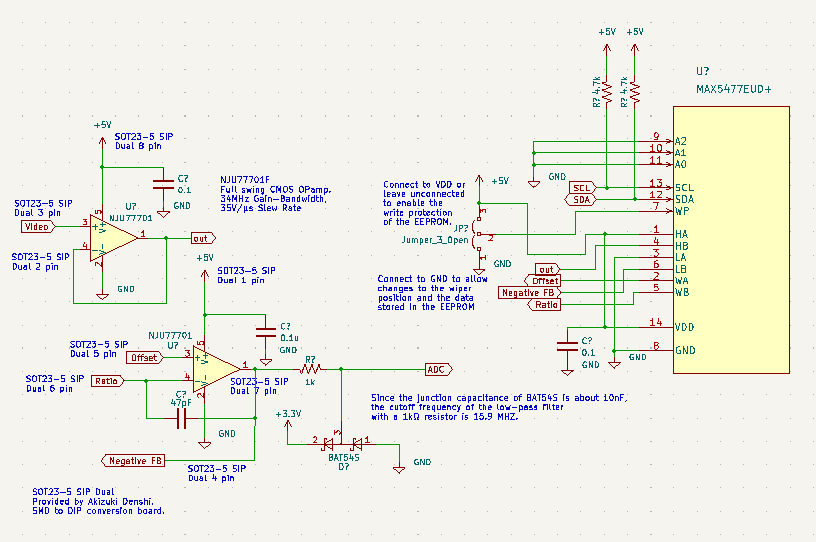
回路図は以前にも示したが、次のとおり、MAX5477回りを新たに示す。
設計ミスを修正した新しい基板を発注するための準備をしているのだが、新しい基板ではMAX5477のI²Cアドレスを固定にした。パッドの場所が確保できなかった。
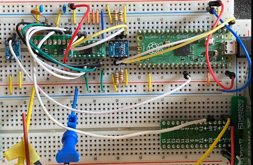
実際のテストの様子。
ホコリだらけだ、MAX5477は5Vで動かすので、3.3VのRaspberry Pi PicoからI²C接続するにはレベル変換が必要。実際には8chのFXMA108を用いているのであるが、実験では2chのFXMA2102を使った秋月電子のI²Cバス用双方向電圧レベル変換モジュールを使っている。
測定結果
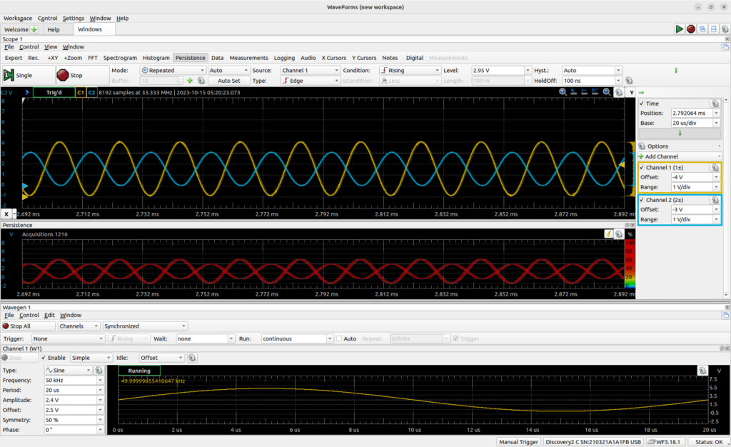
振幅が±2.5Vの正弦波にオフセット2.5Vで、0V〜5Vの正弦波を生成して入力に入れた(黄色)。水色のラインが出力信号で、反転増幅回路なので反転している。増幅率を0.6に設定したので、5Vの振幅が3Vになっている。
まとめ
ほぼ、目的通りの挙動を示していると思う。ただし、数百キロヘルツ程度の信号であれば特に問題なさそうであるが、メガヘルツになるとちょっと波形が乱れてくるようだ。PicoのMicroPythonの場合、300ksps(45ksps程度)でしかVideo信号は取り込めないので、特に問題になることはなさそうである。
電子工作を初めてから、オペアンプを本格的に初めて使った。色々勉強になった。
参考文献
- 定本 OPアンプ回路の設計―再現性を重視した設計の基礎から応用まで (定本シリーズ)
- 浜松ホトニクス ミニ分光器 マイクロシリーズ C12880MA データシート
- 日清紡マイクロデバイス NJM77701F 1回路入り34MHz、35V/us、低ノイズ入出力フルスイング高速CMOSオペアンプ